Fixin’ a Glitchin’ ESP8266 – or How to use two FNB58 as a Dual Channel Oscilloscope.
So I’ve been using the ESP8266 for quite a while now within the confines of the Arduino environment. It’s been hobby stuff – playing with humidity and temperature sensors, making WiFi data loggers, controlling strings of addressable LEDs using the awesome WLED firmware, and quite a lot if other gimmicky stuff.
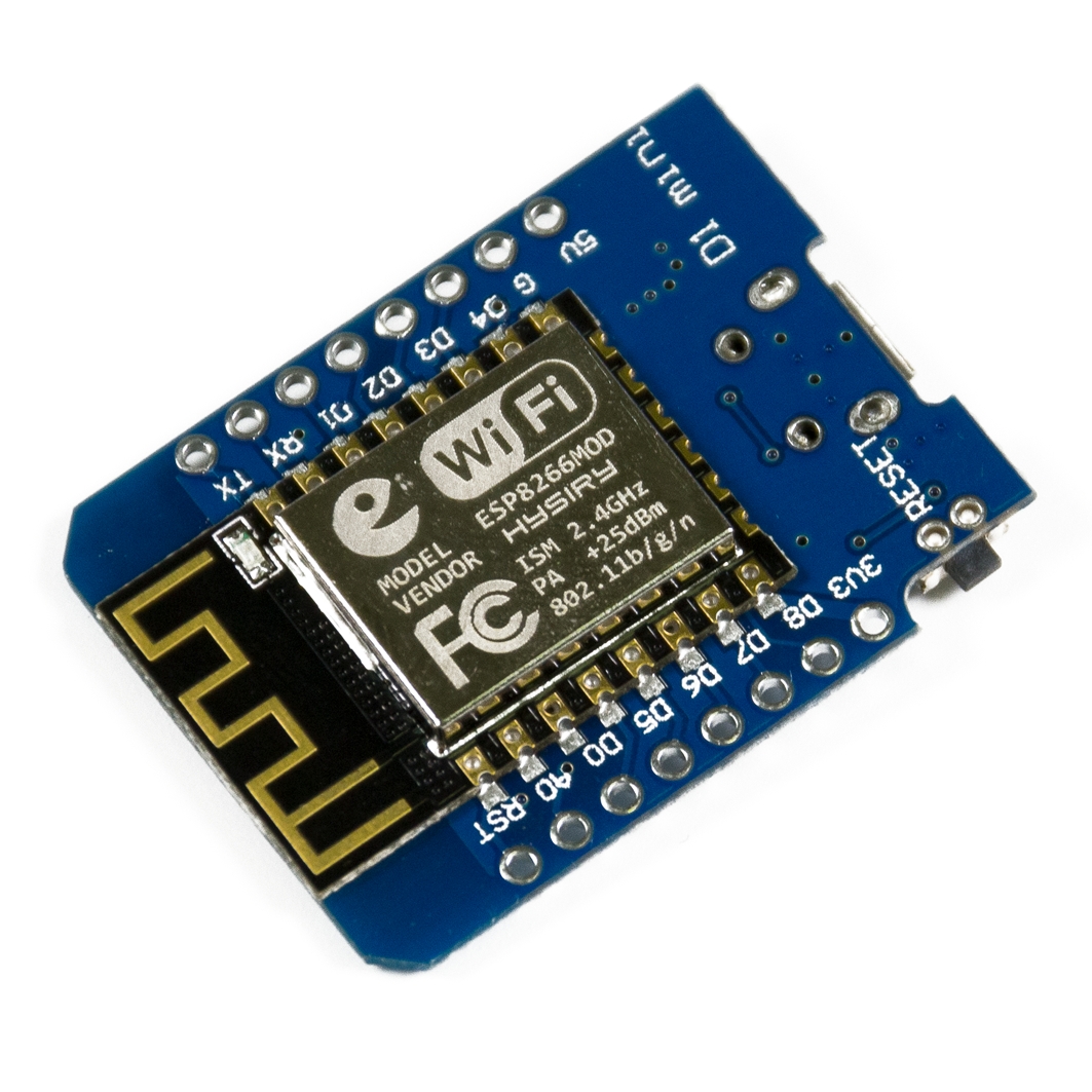
Left: Wemos Wroom-02. Right: Wemos D1 Mini
To continue blowing money on an expensive hobby, this time around I purchased the compact Wemos D1 Mini. This was a clone board from a local supplier in India. As with most of my purchases – you buy the board after getting inspired by a YouTube video or an Instructable, but by the time the components arrive, you’re drowning under piles of mundane 9-5 work.
This Wemos board sat in my parts bin for a few months before I pulled it out. I wanted to try out the ultra low power, deep sleep modes of the ESP8266, so I wrote up some code and threw it onto a Wroom2 board. Things worked fine, and since I was looking for something physically smaller, I pulled out the D1 Mini. After burning the code, I waited for the board to connect to WiFi and write data to a Google spreadsheet. When it didn’t, I began the task of troubleshooting.
Initially, I thought the issue was something to do with my WiFi - my WiFi is provided by the building, and I need to access a captive login page, authenticate my device, and can only proceed after this. This is quite difficult to do with an ESP8266, and the additional code complexity is unnecessary in my opinion. The authentication/registration is MAC-based, so I use a TP-Link MR3020 running OpenWRT, clone the MAC of the ESP8266, use my laptop to log in via the TP Link router, after which the ESP8266 MAC gets registered onto the network. Yeah, tedious.
Logging in through a captive portal by MAC Spoofing
But after spending an hour or so trying to find out if the MAC was being blocked, I then moved on to thinking it was something to do with Google Scripts’ authentication – it’s changed in the past, or required re-validation, since the ESP module is treated like a separate device logging into your account. I managed to eliminate any pathway issues to Google Scripts by easily achieving what I wanted to using the Wroom-02.
Then I started looking at the serial monitor, which showed a crash log with “rst cause” and “boot mode”, as well as a stack trace. I decided to take a closer look at the debug output every time the ESP8266 reset. I saw that the reset code was not consistent. It would also spit out random strings of serial, indicative of a lockup. The ESPExecptionDecoder plugin for the Arduino environment is a handy tool to aid with debugging.
Crash logs – the reset cause would randomly change from ‘normal’ reset to ‘power cycle’
By this point I thought that the seller had given me a fake ESP8266 chip. Despite these chips being literally “as cheap as chips” it was entirely possible that the seller himself, had been a victim of fake chips from the black market.
Something I noticed was that occasionally, Google sheets would populate a sensor value. So it appeared that the chip was not ‘entirely fake’. Could this have something to do with the power supply? I was powering the device from my laptop USB port – I tried swapping to shorter, thicker USB cables. I even jammed a 470uF electrolytic on the 5v rail. This didn’t really improve anything.
I went so far as to desolder and replace the CH340G chip as well as desoldered and replace the ESP8266 module with a fresh one I had around – talk about trying everything!
I finally came across Reddit threads pointing to the culprit – an underpowered 3.3v regulator. Of course, that was it! The original D1 Mini schematic specifies a Richtek RT9013 500mA regulator. The regulator on my board was a 150mA Torex XC6204 with markings 4B2X.
The SOT23-5 is the under-spec’d XC6204
After smacking myself for being dumb enough to check the 5v rail, but forgetting to consider that there was a 3.3v rail on the board too, I proceeded to make some measurements on the Wroom board, since I knew that was working well. In the graphic below, the blue trace is the 5v rail, the green is the 3.3v rail, and the red is the current. Although the first time the board connects to WiFi is not very obvious, every power on and connection attempt from 105 seconds onwards is clear. You can identify the surge in current every 60 seconds or so when the ESP8266 tries to wake from deep sleep, transmit a packet over WiFi, and then shutdown for a minute. Current spikes go to more than 450mA on this board.
Expected Signatures: Current (Red), 5v Rail (Blue), 3.3v Rail (Green)
I used a FNIRSI FNB58 USB tester to check for the current and voltage profile. Not having a dual trace oscilloscope handy, I resorted to a bit of a hack. The FNB58 is capable of measuring voltage and current in both directions. Meaning, the ‘output’ can measure a voltage. Since I had two FNB58s, I planned to use one to monitor the voltage on the 3.3v rail, and the other, to measure current and voltage on the 5v rail. I cut the end off a USB cable, connected the ‘A’ part into the output of one of the FNB58s, disconnected the FNB58 from source power, and left only the data logging / device power cable in, and used crocodile clips to attach the bare ends of the USB wires onto the 3.3v rail of the D1 Mini. This allowed me to see what was happening to the voltage. I used the provided PC software to log data – each FNB58 is logged in a separate window. I did have get creative on how to sync the data from two logs – the way I did this was to start the recording on both FNB58s, and then plug in the power to the D1 Mini. This allowed me to synchronize the rising current from the 5v log to the rising voltage on the 3.3v log.
The Wemos D1 Mini being tested. The FNB58 monitoring the 5v rail is naked because it went through a teardown
FNIRSI’s USBMeter logging software creates a cfn file. didim99 has written a simple python utility to convert these cfn files to csv. After importing the CSV files into excel, I offset and aligned the values with respect to time, and then plotted them.
Logs: 5v Rail (Blue), 3.3v Rail (Green), Current (Red)
A brief explanation of the plots above - three tests were done:
- Test 1 – upper track – with the original XC6204 regulator and a 15uf capacitance on the output of the regulator
- Test 2 – middle track – with 100uf extra added onto the 3.3v output of the regulator
- Test 3 – bottom track – with the XC6204 regulator replaced by a TPS73633
Left image: all logged traces (5v, 3.3v, current), middle image: only voltages (5v, 3.3v), right image: only current
The issue was very obviously an underpowered 3.3v regulator that was unable to keep the rail suitably powered. The 3.3v rail with 15uf of decoupling (V3_15) clearly drops out. Although not shown on the graph, it dropped several time to below 2.6v – below the reset / brownout threshold for the ESP8266. You can also see lots of noise on the 5v rail (V5_15), and the current trace (C5_15).
I had a few options – I could replace the XC6204 with an RT9013 or equivalent, or I could throw a butt-load of capacitors onto the 3.3v rail. Simply jamming a 470uF electrolytic’s leads across the 3.3v and Gnd pins, ghetto-style, was good enough to get the D1 Mini working; pulling off the capacitor resulted in the earlier mentioned streams of serial gibberish and crash logs. This behaviour gave me enough confidence that it was indeed the regulator at fault.
Left: Streams of gibberish being spewed out of the serial port
Right: Ghetto-style decoupling on the 3.3v rail. Naturally, this is not as effective if placed across the 5v rail
Since I wanted to validate, I sucked off some tantalums from a junk board I had lying around and soldered a 15uF and a 100uF from 3.3v to Gnd, while simultaneously placing an order for a couple of Texas Instruments TPS73633.
When nothing works, throw a capacitor on it! Tantalum capacitor with a bodge wire soldered from the 3.3v rail to Gnd
Throwing on the 100uf capacitor significantly improves voltage and current response. There are still spikes on the 5v and the 3.3v rail is about 3.23v, but the system works.
The TPS73633 chips are 400mA 3.3v LDOs with a drop out of only 75mV; if ordered in a SOT23-5 package, these are pin-compatible with the XC6204 / RT9013 – perfect for the job. I didn’t want to use an LM1117-3.3v due to the high drop-out voltage of 1.1v, and the incompatible SOT-223 package – the advantage of this chip would have been 1A of available current. Comparison of specs below:
| XC6204 | RT9013 | TPS73633 | AMS1117 | |
| Operating Voltage | 2-10v | 2.2-5.5v | 1.7-5.5v | 4.75-15v |
| Max Current | 150mA | 500mA | 400mA | 1000mA |
| Dropout | 200mV @ 100mA | 250mV @ 500mA | 75mV @ 400mA | 1100mV @ 1000mA |
| Quiescent current | 70uA | 25uA | 400uA | 5000uA |
Left: the Wemos D1 R2. Right: Wemos D1 Mini with the TPS73633 soldered on.
After receiving and soldering the TPS73633, and going back to the schematic capacitors left the board working perfectly happily. Looking at the log, all traces (V5_15_reg, V3_15_reg, C5_15_reg) are much cleaner, and the 3.3v rail averages 3.24v.
Interestingly, my Wemos D1 R2 Arduino Uno style board has the same XC6204 regulator (markings 4A2D). But it also has a log of capacitive decoupling on its output.
Now to get down to actually building my project