Showing posts with label ESP8266. Show all posts

Tuesday, May 30, 2023

Fixin’ a Glitchin’ ESP8266

Fixin’ a Glitchin’ ESP8266 – or How to use two FNB58 as a Dual Channel Oscilloscope.

So I’ve been using the ESP8266 for quite a while now within the confines of the Arduino environment. It’s been hobby stuff – playing with humidity and temperature sensors, making WiFi data loggers, controlling strings of addressable LEDs using the awesome WLED firmware, and quite a lot if other gimmicky stuff.
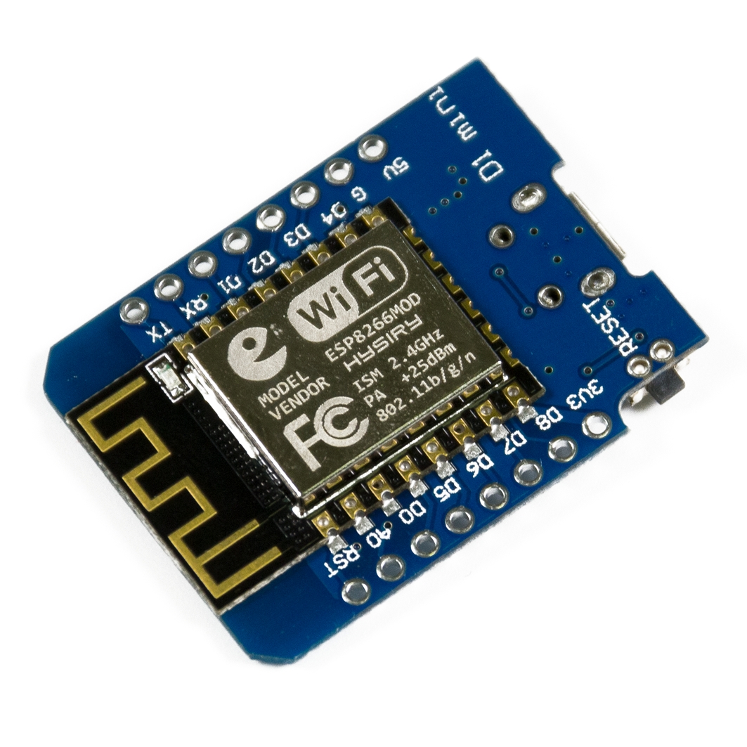
 

IMG_4273Купить WEMOS D1 mini Pro Arduino/ESP/Raspberry Pi (Доставка РФ,СНГ)

Left: Wemos Wroom-02. Right: Wemos D1 Mini


To continue blowing money on an expensive hobby, this time around I purchased the compact Wemos D1 Mini. This was a clone board from a local supplier in India. As with most of my purchases – you buy the board after getting inspired by a YouTube video or an Instructable, but by the time the components arrive, you’re drowning under piles of mundane 9-5 work.

This Wemos board sat in my parts bin for a few months before I pulled it out. I wanted to try out the ultra low power, deep sleep modes of the ESP8266, so I wrote up some code and threw it onto a Wroom2 board. Things worked fine, and since I was looking for something physically smaller, I pulled out the D1 Mini. After burning the code, I waited for the board to connect to WiFi and write data to a Google spreadsheet. When it didn’t, I began the task of troubleshooting.

Initially, I thought the issue was something to do with my WiFi - my WiFi is provided by the building, and I need to access a captive login page, authenticate my device, and can only proceed after this. This is quite difficult to do with an ESP8266, and the additional code complexity is unnecessary in my opinion. The authentication/registration is MAC-based, so I use a TP-Link MR3020 running OpenWRT, clone the MAC of the ESP8266, use my laptop to log in via the TP Link router, after which the ESP8266 MAC gets registered onto the network. Yeah, tedious.


image

Logging in through a captive portal by MAC Spoofing


But after spending an hour or so trying to find out if the MAC was being blocked, I then moved on to thinking it was something to do with Google Scripts’ authentication – it’s changed in the past, or required re-validation, since the ESP module is treated like a separate device logging into your account. I managed to eliminate any pathway issues to Google Scripts by easily achieving what I wanted to using the Wroom-02.

Then I started looking at the serial monitor, which showed a crash log with “rst cause” and “boot mode”, as well as a stack trace. I decided to take a closer look at the debug output every time the ESP8266 reset. I saw that the reset code was not consistent. It would also spit out random strings of serial, indicative of a lockup. The ESPExecptionDecoder plugin for the Arduino environment is a handy tool to aid with debugging.


image

Crash logs – the reset cause would randomly change from ‘normal’ reset to ‘power cycle’


By this point I thought that the seller had given me a fake ESP8266 chip. Despite these chips being literally “as cheap as chips” it was entirely possible that the seller himself, had been a victim of fake chips from the black market.

Something I noticed was that occasionally, Google sheets would populate a sensor value. So it appeared that the chip was not ‘entirely fake’. Could this have something to do with the power supply? I was powering the device from my laptop USB port – I tried swapping to shorter, thicker USB cables. I even jammed a 470uF electrolytic on the 5v rail. This didn’t really improve anything.

I went so far as to desolder and replace the CH340G chip as well as desoldered and replace the ESP8266 module with a fresh one I had around – talk about trying everything!

I finally came across Reddit threads pointing to the culprit – an underpowered 3.3v regulator. Of course, that was it! The original D1 Mini schematic specifies a Richtek RT9013 500mA regulator. The regulator on my board was a 150mA Torex XC6204 with markings 4B2X.


IMG_4275

The SOT23-5 is the under-spec’d XC6204


After smacking myself for being dumb enough to check the 5v rail, but forgetting to consider that there was a 3.3v rail on the board too, I proceeded to make some measurements on the Wroom board, since I knew that was working well. In the graphic below, the blue trace is the 5v rail, the green is the 3.3v rail, and the red is the current. Although the first time the board connects to WiFi is not very obvious, every power on and connection attempt from 105 seconds onwards is clear. You can identify the surge in current every 60 seconds or so when the ESP8266 tries to wake from deep sleep, transmit a packet over WiFi, and then shutdown for a minute. Current spikes go to more than 450mA on this board.


image

Expected Signatures: Current (Red), 5v Rail (Blue), 3.3v Rail (Green)


I used a FNIRSI FNB58 USB tester to check for the current and voltage profile. Not having a dual trace oscilloscope handy, I resorted to a bit of a hack. The FNB58 is capable of measuring voltage and current in both directions. Meaning, the ‘output’ can measure a voltage. Since I had two FNB58s, I planned to use one to monitor the voltage on the 3.3v rail, and the other, to measure current and voltage on the 5v rail. I cut the end off a USB cable, connected the ‘A’ part into the output of one of the FNB58s, disconnected the FNB58 from source power, and left only the data logging / device power cable in, and used crocodile clips to attach the bare ends of the USB wires onto the 3.3v rail of the D1 Mini. This allowed me to see what was happening to the voltage. I used the provided PC software to log data – each FNB58 is logged in a separate window. I did have get creative on how to sync the data from two logs – the way I did this was to start the recording on both FNB58s, and then plug in the power to the D1 Mini. This allowed me to synchronize the rising current from the 5v log to the rising voltage on the 3.3v log.


image

The Wemos D1 Mini being tested. The FNB58 monitoring the 5v rail is naked because it went through a teardown


FNIRSI’s USBMeter logging software creates a cfn file. didim99 has written a simple python utility to convert these cfn files to csv. After importing the CSV files into excel, I offset and aligned the values with respect to time, and then plotted them.


All_reducedVoltages_reducedCurrents_reduced

Logs: 5v Rail (Blue), 3.3v Rail (Green), Current (Red)

A brief explanation of the plots above - three tests were done:

  • Test 1 – upper track – with the original XC6204 regulator and a 15uf capacitance on the output of the regulator
  • Test 2 – middle track – with 100uf extra added onto the 3.3v output of the regulator
  • Test 3 – bottom track – with the XC6204 regulator replaced by a TPS73633

Left image: all logged traces (5v, 3.3v, current), middle image: only voltages (5v, 3.3v), right image: only current


The issue was very obviously an underpowered 3.3v regulator that was unable to keep the rail suitably powered. The 3.3v rail with 15uf of decoupling (V3_15) clearly drops out. Although not shown on the graph, it dropped several time to below 2.6v – below the reset / brownout threshold for the ESP8266. You can also see lots of noise on the 5v rail (V5_15), and the current trace (C5_15).

I had a few options – I could replace the XC6204 with an RT9013 or equivalent, or I could throw a butt-load of capacitors onto the 3.3v rail. Simply jamming a 470uF electrolytic’s leads across the 3.3v and Gnd pins, ghetto-style, was good enough to get the D1 Mini working; pulling off the capacitor resulted in the earlier mentioned streams of serial gibberish and crash logs. This behaviour gave me enough confidence that it was indeed the regulator at fault.

Screenshot 2023-05-27 222151IMG_4280

Left: Streams of gibberish being spewed out of the serial port
Right: Ghetto-style decoupling on the 3.3v rail. Naturally, this is not as effective if placed across the 5v rail

Since I wanted to validate, I sucked off some tantalums from a junk board I had lying around and soldered a 15uF and a 100uF from 3.3v to Gnd, while simultaneously placing an order for a couple of Texas Instruments TPS73633.

IMG_4272

When nothing works, throw a capacitor on it! Tantalum capacitor with a bodge wire soldered from the 3.3v rail to Gnd


Throwing on the 100uf capacitor significantly improves voltage and current response. There are still spikes on the 5v and the 3.3v rail is about 3.23v, but the system works.

The TPS73633 chips are 400mA 3.3v LDOs with a drop out of only 75mV; if ordered in a SOT23-5 package, these are pin-compatible with the XC6204 / RT9013 – perfect for the job. I didn’t want to use an LM1117-3.3v due to the high drop-out voltage of 1.1v, and the incompatible SOT-223 package – the advantage of this chip would have been 1A of available current. Comparison of specs below:

XC6204 RT9013 TPS73633 AMS1117
Operating Voltage 2-10v 2.2-5.5v 1.7-5.5v 4.75-15v
Max Current 150mA 500mA 400mA 1000mA
Dropout 200mV @ 100mA 250mV @ 500mA 75mV @ 400mA 1100mV @ 1000mA
Quiescent current 70uA 25uA 400uA 5000uA


IMG_4274IMG_4283

Left: the Wemos D1 R2. Right: Wemos D1 Mini with the TPS73633 soldered on.


After receiving and soldering the TPS73633, and going back to the schematic capacitors left the board working perfectly happily. Looking at the log, all traces (V5_15_reg, V3_15_reg, C5_15_reg) are much cleaner, and the 3.3v rail averages 3.24v.

Interestingly, my Wemos D1 R2 Arduino Uno style board has the same XC6204 regulator (markings 4A2D). But it also has a log of capacitive decoupling on its output.

Now to get down to actually building my project Open-mouthed smile

Saturday, January 2, 2016

Eye-Oh-Tee

I have finally jumped onto the IoT bandwagon, so this is a better-late-than-never kinda post.

IoT – the Internet of Things, is a revolution of sorts. IoT devices promise to connect all devices to the internet. Check out any of today’s consumer electronic devices – thermometers, humidity sensors, power meters, which traditionally lend themselves well to such ‘internet-linking’, as well as non-conventional devices – toasters that tweet when your toast is done, refrigerators that Whatsapp you when you’re low on milk, and potties that change your FB status to:

Checked in….Emptied bowels ::feeling relieved:: image

(There’s a strong debate that the poo emoji is actually an ice cream, but I digress). Here’s an interesting article to what 2016 has in store for us (and if you’re reading this in 2020 for some reason, don’t snigger at old tech!).

IoT devices have been around for quite a while now, however only last year, with the ‘discovery’ of the ESP8266, did they become cheap and accessible to everyone. How cheap and how accessible? To quote Brian Jepson from Make - “This is inexpensive enough to be very much in the territory of ‘thousands of sensors-launched-out-of-a-cannon’-cheap.


The ESP8266

The ESP8266 is an amazing device. Made by Espressif Systems, the chip is a super-cheap WiFi device, that can be configured as a host (ie Access Point), or a client. Although the ESP8266 itself comes in an evil 0.5mm-pitch QFN with no on-chip flash memory, you can find complete modules with external SPI flash memory, status LEDs, pins broken out, selling for under USD5 at the time of writing (Dec 2015). Infact a bare-bones ready-to-start module can be had for Rs.270 (USD4) in India.

When I got back home for the vacations, I decided to give myself an early Christmas gift, and picked up an ESP-01 module, and an ESP12F module, along with a few other things.

IMG_2378
Christmas comes early! 3.3v regulators, adapter boards, ESP8266 modules (ESP12F and ESP-01), and tweezer multimeter probes for SMD stuff

Everything in the picture was bought from Inkocean (other than the mini solderless breadboard, the adapter board in the middle, and the LED).

The white adapter board breaks out the pins of the ESP12F module into a convenient breadboard-compatible pitch. The ESP-01 module is not really solderless breadboard compatible due to its dual-row pin header. To use this module, I had to build an adapter board, which you see in the middle of the picture.


Getting Started – AT Commands

Out of the box, the ESP-01 responds to AT modem commands sent over 3.3v UART TTL signals. The AT commands allow you to talk to the chip, view WiFi networks, connect to a network, and do several other things.

I used an FTDI Basic (you could use any USB-TTL serial converter – the CP2102/MCP2200/CH340, which are cheaper) and a simple terminal program @ 115200bps to communicate. On power up, the module initially sends some seemingly random characters (at 115200bps), but if you set your terminal program to 76800 baud (2*38400), you should see some meaningful debug data.

AT+RST soft-resets the WiFi modem
AT+GMR shows the firmware version
AT+CWLAP lists all access points
AT+CWJAP=”SSID”,”Password” joins an access point
AT+CIFSR shows the IP address once connected

Connecting to a network was pretty easy, and I was able to ping the module from my laptop’s command prompt in a matter of minutes.

Pinouts connections
Simple interface circuit


The Adapter Board

With its AT command set, the ESP-01 plays nice with almost any microcontroller capable of reading and sending serial strings. However, IMHO, its real power lies in the fact that it can be re-programmed using nodeMCU (Lua scripting), or the Arduino IDE (Processing), or even a BASIC interpreter. Since I am already familiar with the Arduino environment, I chose to experiment using this.

The ESP8266 can be put into various modes by setting combinations of I/O pins high or low, thus allowing it to boot from SPI flash memory (normal), or go into bootloader mode to update firmware (via UART Rx/Tx), or boot from an SD card.

To use the 8266 with Arduino code, we obviously need to put it into bootloader mode. This is done by momentarily pulling GPIO0 to ground while resetting the chip (pull RST to ground or cycle power). Doing this multiple times with dangly bits of wire would be tedious, so I made a simple adapter board with appropriate connections:

  • a 3.3v voltage regulator (LM1117-33), since I’m using the 5v FTDI Basic
  • 10k pullup resistor and a button to ground on RST
  • 1k + 2.2k voltage divider resistors on the 8266 Rx, (to divide the 5v TTL UART signals from the Tx of the FTDI)
  • Tx of the 8266 can go straight to the Rx of the FTDI
  • a button to ground on GPIO0
  • CH_PD pulled to Vcc (3.3v)
  • Gnd to ground (where else!). Don’t forget to short the grounds of the USB-to-serial converter and the 8266.
  • GPIO2 can remain floating

IMG_2375 IMG_2376
Left:
top of the adapter board, and Right: bottom of the board. All pins of the vertical header are not connected; only GPIO2 and Gnd are connected at the moment. I plan to breakout GPIO0, GPIO1 (Tx), GPIO3 (Rx), and 3.3v later


Basic Arduino Sketch

I had a few problems getting the adapter board to work (details in the next section), but once I got it running, I threw the standard hello-world/blinky test code onto the 8266 using the following Arduino code:

void setup(void)
{
	pinMode(2, OUTPUT);
	Serial.begin(115200);
	Serial.print("Setup done\r\n");
}

void loop(void)
{
	digital.Write(2,HIGH);
	Serial.println("Testing...");
	delay(500);
	digital.Write(2,LOW);
	delay(500);
} 

And when this worked flawlessly, I tried a webserver demo:

#include <ESP8266WiFi.h>
#include <ESP8266WebServer.h>
 
const char* ssid	 = "my_SSID";
const char* password = "my_password";
 
ESP8266WebServer server(80);


String webString="";
// String to display
 
void handle_root()
{
	server.send(200, "text/plain", "Hello from the ESP8266. Use /on or /off");
	delay(100);
}
 
void setup(void)
{
	pinMode(2, OUTPUT);
	Serial.begin(115200);
	// Serial monitor

	WiFi.begin(ssid, password);
	// Connect to WiFi network
	Serial.print("\n\r \n\rConnecting....");
 
	// Wait for connection
	while (WiFi.status() != WL_CONNECTED)
	{
		delay(500);
		Serial.print(".");
	}
	Serial.println("");
	Serial.print("Connected to ");
	Serial.println(ssid);
	Serial.print("IP address: ");
	Serial.println(WiFi.localIP());

	// clauses below handle different
	// subpages
	server.on("/", handle_root);

	server.on("/on", []()
	{
		webString="LED ON";
		server.send(200, "text/plain", webString);
		// send to browser
		digitalWrite(2, HIGH);
	});
 
	server.on("/off", []()
	{
		webString="LED OFF";
		server.send(200, "text/plain", webString);
		// send to browser
		digitalWrite(2, LOW);
	});

	server.begin();
	Serial.println("HTTP server started");
}

void loop(void)
{
	server.handleClient();
}

The connected serial terminal told me that my 8266 acquired an IP of 172.20.10.6. I used my computer’s browser to navigate to this page.

Serial Terminal Landing page
Left: the serial terminal provides a handy debug
Right: the landing page of the webserver

IMG_2480Turning the LED ON and OFF

Going to 172.20.10.6/on turns the LED on.

Going to 172.20.10.6/off turns the LED off.


Problems/Issues

I shouldn’t really call it a ‘problem’, but for lack of a better word, that’s what it is – the ESP-01 module has got 0.1in-spaced dual-row pin headers. This is not convenient for solderless breadboard prototyping. There are a few hacks/mods available online, but I decided to go the adapter board way.

The adapter board was not to difficult to make, and I faced no real problems while soldering. The board was a dual-sided proto-board, which made things a little easier. The LM1117 was soldered on the bottom side, as were the tiny 0201 resistors, scrounged from my junk box.

I had initially gone with a 10k pullup on the RST pin of the ESP-01, and a 10k-22k voltage divider on the FTDI’s Tx line. The choice of resistors for the voltage divider was the cause of a lot of grief. I was able to see all the debug messages coming from the ESP-01 (since the ESP’s Tx was directly connected to the FTDI’s Rx), but for some reason, no messages were being received by the ESP-01. I changed baud rates, checked and re-checked my circuit, measured voltages, tried a loop-back test with just the adapter board, all of which worked fine; it was just that the module would not respond when queried with an AT command. And since the loop-back test worked, the signal path along with the divider resistors was obviously good.

I had almost concluded that I either had a dud chip, or corrupted firmware, or a chip with a damaged Rx pin, and was about the go down the rabbit’s hole and break out my oscilloscope. Something made me change the divider resistors by an order of magnitude – I swapped the resistors to 1k-2.2k. Maybe the 8266 liked a stiffer drive? This was a bit surprising since the datasheet states that an 8266 input needed just 5nA drive current; the 10k-22k combo was capable of sourcing significantly more than that! I dunnno.

Once I changed the resistors everything worked fine. The chip happily responded to AT queries, and re-programming with Arduino IDE-compiled code was not a problem.

A deeper look into the datasheet showed that I/O pins of the 8266 are internally clamped to 6v. So technically, I could use a single series resistor on the FTDI Tx/8266 Rx and overdrive the Rx pin. The protection diode would do its work and clamp the voltage on the pin to 5.8v. However, I wanted to do things the ‘right’ way.

Apparently, ESP-01s from different manufacturers have different baud rates. Mine defaulted to 115200 for comms, and 76800 for debug. YMMV.


Further Stuff

Obviously, there’s much more you can do with this chip than just turning on and off an LED. The ESP-01 makes available at most 4 GPIOs – GPIO0, GPIO1 (Tx), GPIO2, GPIO3 (Rx) – with caveats.

During development, GPIO1 and GPIO3 may be reserved for UART functions. Connecting external hardware to these pins may interfere with the UART signal levels. You could easily wire up a port expander like the MCP23008/MCP23017 or a serial shift register like the 74HC595.

The ESP12F module breaks out all the pins into an easy breadboard pitch, and if you really want all pins for your custom board, QFN DIY soldering isn’t all that tough.

Happy IoT-ing!


Helpful Links

Arduino + ESP8266:
https://hackaday.io/project/5150-arduino-ide-for-esp8266-quickstart-guide

Another getting started guide:
http://www.madebymarket.com/blog/dev/getting-started-with-esp8266.html

ESP8266 Arduino command reference:
http://arduino.esp8266.com/versions/1.6.5-990-gc8a63ce/doc/reference.html

GPIO allocations:
http://www.esp8266.com/wiki/doku.php?id=esp8266_gpio_pin_allocations

Wiki:
https://en.wikipedia.org/wiki/ESP8266

8266 Community Wiki (very useful):
http://www.esp8266.com/wiki/doku.php?id=start

Visitors